Introduction
STMicroelectronics has spent last couple of years developing their embedded graphics framework called TouchGFX. This very powerful graphics engine makes it possible to include snazzy, smartphone-like screens and widgets into the embedded application, what I feel like becomes defacto a standard nowadays. Along with it, they shipped a lot of dev boards and reference designs, that cover various LCD interfaces and graphical demo applications. While the original documentation as well as the demo applications are truly rich in content, many people, including myself, struggled to run this fantastic piece of software on a custom made setup. Especially on the setup that doesn’t meet specific graphics requirements, such as a dedicated LCD interface, a ton of RAM, high clock frequency, RTOS, etc.
The code I developed on this project can be found here.
Note: I was using TouchGFX Designer v4.15 along with CubeMX v6.1. By the time I have finished editing this post, TouchGFX rolled out the version 4.16. Hopefully, nothing crucial has changed.
My setup
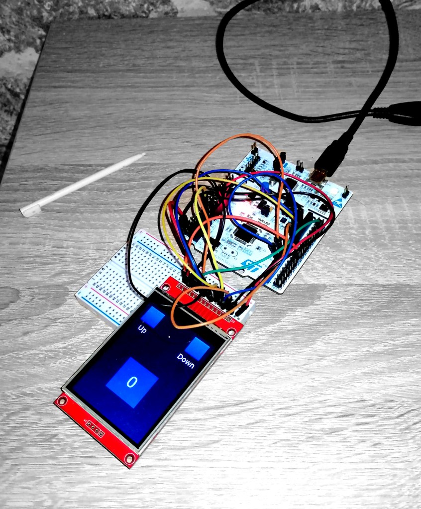
I was using a board I had lying around, Nucleo-F411RE. It is based on STM32F411RET, a moderately powerful Cortex-M4F device that runs at 100MHz. Aside of embedded FPU, it doesn’t offer much. My intention was not to make a high performance graphics project, but to learn how embedded graphics work, for fun.
For the display, I had a “standard” Aliexpress ILI9341 board with 320×240 TFT LCD. Additionally, the board includes a clone chip of XPT2046, a resistive touchscreen controller. The board came preconfigured in SPI interface, different for touchscreen and display. Now, the important part was to have a working library for both of these components. Luckily, the ILI9341 is a rather popular add-on in hobbyist community, so there were plenty available. I went for the one from this repository here. Whatever you use, make sure that it implements the DMA based SPI data transfer, and window-based rendering, i.e. that you can define only a part of the screen to be drawn. This is what official documentation describes as a Board Bring-Up. In my library, these would be functions called ILI9341_SetWindow() and ILI9341_DrawBitmap().
Framebuffer size issue
The framebuffer is a piece of memory that basically corresponds to each pixel on the screen. The framebuffer is updated by the graphics engine to contain the next image to be shown on the display. In the most basic implementation, it’s an integer array of a size equal to the the display resolution. The type of the framebuffer array corresponds to the color depth of the screen. In case of the ILI9341, which has 320×240 pixels and color format RGB565 (16-bit), the framebuffer would be defined as:
uint16_t framebuffer[320x240] = {0};Simple math says the framebuffer would occupy 153,600 bytes of memory, or 150 kB. The board Nucleo-F411RE I’m using only has 128kB of RAM. Hmm, see the issue there? Normally, I’d give up on this board, and started a new project with one of the recommended ones. But, I really wanted to dive in and configure the custom setup, so I kept going.
At first, I started with the TouchGFX implementation on half of the screen only. Somehow, at the time I was pulling my hair with glitches on the screen, STMicro guys released v4.15 that internalizes something called a partial framebuffer strategy. This little feature makes it possible to render the full screen while reducing its memory budget.
Partial framebuffer strategy
Usually, the good graphics project would support two framebuffers: while one is being transferred to the screen, the other is being filled with the data for the next frame. But my board doesn’t support even a single framebuffer. Partial framebuffer strategy splits my framebuffer into three smaller blocks, that will be sequentially overwritten, or rendered to fill a full frame, thus reducing the consumed memory to a third. Naturally, it will also prolong the rendering time by three times as long, but simple embedded application won’t mind it. But to be able to implement it, let’s first check what’s going on under the hood of the TouchGFX.
Inner workings of TouchGFX, briefly
TouchGFX engine works alongside of the main microcontroller application, but is also somehow independent, and runs in its own infinite loop, kind of like a RTOS. That loop consists of three phases:
- Collect events: Detecting events from the touch screen, presses of physical buttons, messages from backend system,
- Update scene model: React to the collected events, updating the positions, animations, colors, images, of the model. Basically, it calculates new values in the framebuffer array in the phase.
- Render scene model: Redraw the parts of the model that has been updated and make them appear on the display

This all happens deep inside the TouchGFX engine, and we do not need to worry too much about it. What we do need to take care of is a wrapping layer of the engine that actually interacts with our main code, so called TouchGFX Abstraction Layer, or AL, for short. The AL must
- synchronize the graphics engine loop with the display transfer – you don’t want the content of the framebuffer changed during the display operation, obviously.
- report touch and physical button events – if we have a working library for buttons or for example XPT2046 touchscreen controller, we need to make it work with TouchGFX somehow
- synchronize framebuffer access – since it is expected that framebuffer will be accessed by DMA or the main application loop, AL must make sure all goes well.
- report the next available framebuffer area – if the engine fills the framebuffer in pieces, like it does in my partial framebuffer application, AL need to keep an eye on which part of it gets written next.
- handle framebuffer transfer to display – this is the most tangible part of the AL, how to actually invoke all those transfer functions from my ILI9341 library.
In other words, this means we need to implement sync signaling to the engine, signaling from the user inputs (buttons or touchscreen), and most importantly, transfer to the LCD. Let’s see how to do that.
Workflow
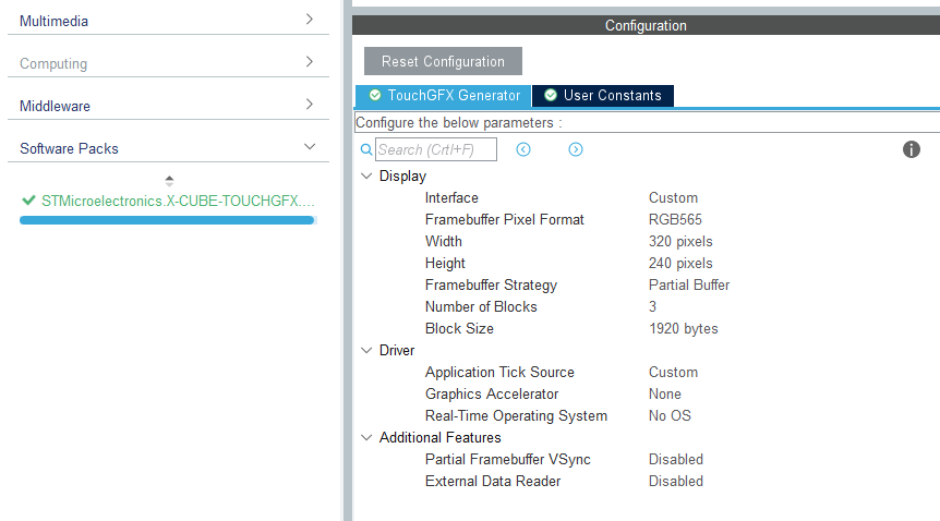
Like any other reasonable STM32 project, this one starts in the CubeMX. After choosing TouchGFX in Software Packs section, select Partial framebuffer strategy, size and color format of the screen, as well as No-OS option. When the code is generated in the standard way, we are presented with the new files that are clearly explained in the official documentation. Briefly,
- the App folder contains initialization and process start functions, nothing interesting here
- the target folder contains the AL functions we need to communicate with the graphics engine – this is where we actually need to change something, and
- target/generated is a read-only zone where generator implements the code based on our settings from the CubeMX. Study it, but don’t change anything in there.
At this point in time, there is no functional code the generated file and the build will obviously fail. But, it doesn’t mean we can’t have fun. Actually, now comes the most fun part, the TouchGFX Designer, the pride and joy of TouchGFX team. We can open it by simply clicking the ApplicationTemplate.touchgfx.part file. This is where we edit the screen, put all the widgets, buttons, sliders whatever you want to see on your screen. There is a pretty good official documentation on how to play with it. I decided to make a simple button counter. The idea is to increase the number in the text box when the “up”-button is pressed, and decrease it, when the “down”-button is pressed. Simple, as I said earlier, it’s only for sake of learning.
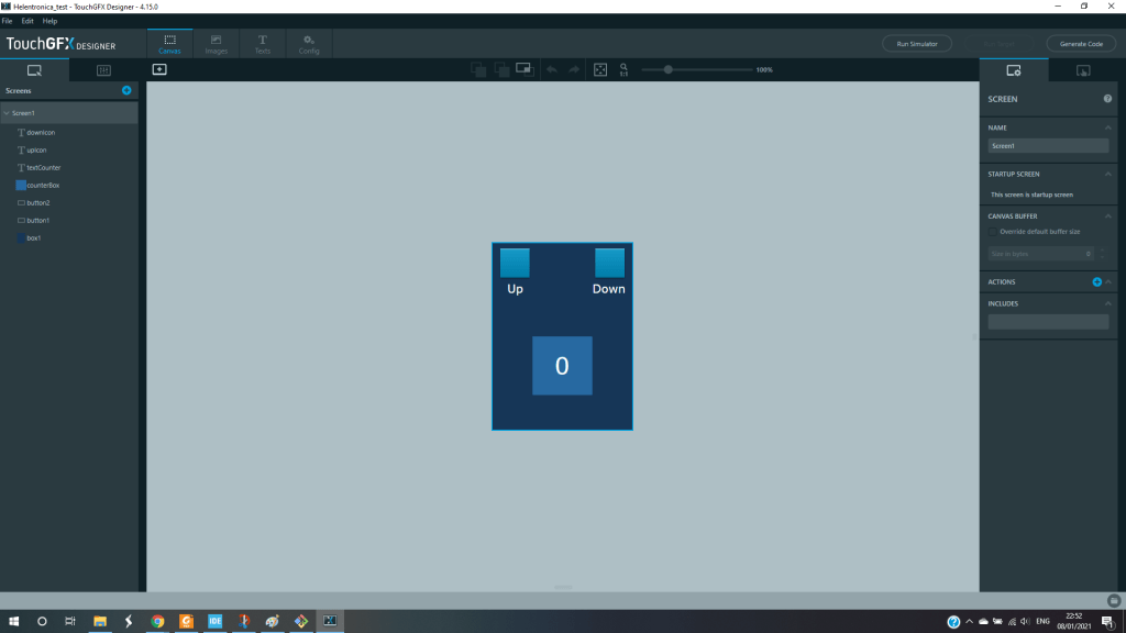
When you’re done having fun with the screen editing and the simulating it, you generate the code again, and new folders appear: assets, build, config, generated, gui, and simulator. This is where the internal workings of TouchGFX engine are implemented, and if you’re here for tutorial, you probably don’t want to mess with those. All the widgets and interactions defined in the UI-Designer, are implemented here in their respective C++ classes, along side heavy memory-occupants, like images, fonts, and photos. Very often, if you’re going to implement some widget functionalities, like buttons in this case, it will require modifying .cpp files in gui folder, mostly in the ScreenView-related classes (well covered in the official tutorial).
Syncing the engine
A good graphics engine is a lot about the timing and syncing. The engine runs its own way to calculate the content of the framebuffer, and, when it’s time to upload the framebuffer data onto the screen, we want the engine to halt. Otherwise, a new frame will start overwriting the one currently being transferred, causing the tearing effect, or simply, bad graphics.
This is what the class OSWrappers is for. Two functions are important in it, OSWrappers::waitForVSync, called by the Engine itself after rendering is complete, and OSWrappers::signalVSync which we need to call when the transfer is done to unblock the engine again.
Since the graphics engine works cyclically, we need some time base, obviously. If we were using an RTOS, there would be some kind of tick that would take care of TouchGFX tasks. In my simple project, there is no RTOS used, so I need to figure something else out. Ideally, the LCD would signal when the transfer is done. But ILI9341 doesn’t do that, so I decided to configure the STM32 timer to call OSWrappers::signalVSync periodically. But how often? Hmm, since there is no way of knowing, I decided to take some reasonable value that is longer than typical SPI transfer, and short enough for pleasant 30 Hz framerate experience. SPI on STM32F411RE has something of 50 MHz clock, meaning that transfer of 150kB framebuffer would take cca 24ms. So, the timer should trigger an interrupt an invoke the signalVsync every 24 – 30ms. On 100MHz clock, the timer would require something like 30000 counts.
Since the function signalVsync is implemented as a part of the C++ class, there is a “C” wrapper function touchgfxSignalVSync() defined in ready-only zone of TouchGFXGeneratedHAL.cpp:
extern "C"
void touchgfxSignalVSync(void)
{
/* VSync has occurred, increment TouchGFX engine vsync counter */
touchgfx::HAL::getInstance()->vSync();
/* VSync has occurred, signal TouchGFX engine */
touchgfx::OSWrappers::signalVSync();
}
I have set the timer TIM2 to generate the interrupt every 30000 clock cycles. The interrupt callback function then calls touchgfxSignalVSync(), periodically.
extern void touchgfxSignalVSync(void);
void HAL_TIM_PeriodElapsedCallback(TIM_HandleTypeDef *htim)
{
if (htim->Instance == TIM2) {
touchgfxSignalVSync();
}
if (htim->Instance == TIM1) { }
}
But, how to actually put the data onto the screen?
When the engine is done rendering, i.e. when the data is written into the framebuffer, it is up the AL to transfer the data to the LCD. It takes a couple of steps to do that. First, we need to check if something is already transferring. If not, we need to invoke the actual transfer functions. Let’s see how it looks like in the source code.
The TouchGFX engine “flushes” the data from the framebuffer to the AL, using the function TouchGFXHAL::flushFrameBuffer(Rect& rect), defined in the file TouchGFXHAL.cpp like this:
void TouchGFXHAL::flushFrameBuffer(const touchgfx::Rect& rect)
{
// Calling parent implementation of flushFrameBuffer(const touchgfx::Rect& rect).
//
// To overwrite the generated implementation, omit call to parent function
// and implemented needed functionality here.
// Please note, HAL::flushFrameBuffer(const touchgfx::Rect& rect) must
// be called to notify the touchgfx framework that flush has been performed.

TouchGFXGeneratedHAL::flushFrameBuffer(rect);
}
We see that this function calls the one with the same name, but in the parent-class TouchGFXGeneratedHAL, in the read-only area. In it, we see the actual flush function, generated by the TouchGFX Generator that takes our partial framebuffer strategy into consideration:
void TouchGFXGeneratedHAL::flushFrameBuffer(const touchgfx::Rect& rect)
{
HAL::flushFrameBuffer(rect);
// Once flushFrameBuffer() is called by the framework a block is already for transfer
// Mark it ready for transfer and transmit it if user defined method isTransmittingData() does not return false
// If data is not being transmitted, transfer the data with user defined method transmitFrameBufferBlock().
frameBufferAllocator->markBlockReadyForTransfer();
if (!touchgfxDisplayDriverTransmitActive())
{
touchgfx::Rect r;
// Get pointer to block buffer and coordinates of the rect
const uint8_t* pixels = frameBufferAllocator->getBlockForTransfer(r);
// Start transmission of the block
touchgfxDisplayDriverTransmitBlock((uint8_t*)pixels, r.x, r.y, r.width, r.height);
}
}
This piece of code communicates what’s going on with the graphics engine. It starts by calling the super-parent class method HAL::flushFrameBuffer(rect) that actually brings framebuffer data from the depths of the engine. Because this is the partial framebuffer strategy, the framebuffer is going to be flushed, block by block. The current block is “marked” ready for transfer on line frameBufferAllocator->markBlockReadyForTransfer();
Now comes the user part: we check the function touchgfxDisplayDriverTransmitActive(). This function is supposed to be written by the user and it should check if the data is currently being transmitted. It should work as a simple boolean flag, returing true or false. No brainer. My implementation is like this:
uint32_t touchgfxDisplayDriverTransmitActive(void)
{
return isTransmittingData;
}
where the flag isTransmittingData is globaly defined and set to zero by default:
static uint8_t isTransmittingData = 0;I’ll show in a second how this flag is changed. If there is no transfer currently going on, the allocated block of the framebuffer gets pointed to the variable pixels:
const uint8_t* pixels = frameBufferAllocator->getBlockForTransfer(r);Now the key part – transferring the block to the LCD by implementing the function touchgfxDisplayDriverTransmitBlock(). The implementation should consider writing the data in form of window-based pixel data. So, ILI9341 library should have something that lets user define the window of the screen to write to. My implementation looks like this:
void touchgfxDisplayDriverTransmitBlock(uint8_t* pixels, uint16_t x, uint16_t y, uint16_t w, uint16_t h)
{
isTransmittingData = 1;
ILI9341_SetWindow(x, y, x+w-1, y+h-1);
ILI9341_DrawBitmap(w, h, pixels);
}
See how I changed that isTransmittingData flag there? Now, when the graphics engine loop calls the flushFrameBuffer() function again, it wont interrupt my transfer.
There is another comment in the TouchGFXGeneratedHAL.cpp file that says:
A user must call touchgfx::startNewTransfer(); once touchgfxDisplayDriverTransmitBlock() has successfully sent a block. E.g. if using DMA to transfer the block, this could be called in the "Transfer Completed" interrupt handler.The tutorial mentions that in partial framebuffer strategy new data transfer is up to user’s implementation, and here it comes. When the data block is transferred, we need to start sending the next block. This is what happens inside the startNewTransfer() function inside TouchGFXGeneratedHAL.cpp.
// A user must call touchgfx::startNewTransfer(); once transmitFrameBufferBlock() has successfully sent a block.
void startNewTransfer()
{
FrameBufferAllocator* fba = HAL::getInstance()->getFrameBufferAllocator();
// Free the previous transmitted block, marking it ready for rendering
fba->freeBlockAfterTransfer();
if (fba->hasBlockReadyForTransfer())
{
touchgfx::Rect r;
// Get pointer to block buffer and coordinates of the rect
const uint8_t* pixels = fba->getBlockForTransfer(r);
// Start transmission of the block
touchgfxDisplayDriverTransmitBlock((uint8_t*)pixels, r.x, r.y, r.width, r.height);
}
}
It looks very similar to the flushFrameBuffer function. But, when to call it? Great question! We know that ILI9341 library uses DMA to feed the data to the LCD. Now, when the DMA is finished, an HAL_SPI_TxCpltCallback automatically invoked and given to the user to clean up the data. This is what I did:
void HAL_SPI_TxCpltCallback(SPI_HandleTypeDef *hspi)
{
if (hspi->Instance == SPI1) {
ILI9341_EndOfDrawBitmap();
isTransmittingData = 0;
DisplayDriver_TransferCompleteCallback();
}
}
In there, I clean up the data, reset the flag and call this funny function DisplayDriver_TransferCompleteCallback(). Wait, what now? Okay, quick glance to TouchGFXGeneratedHAL.cpp shows that it is actually a wrapper for the startNewTransfer(). Ok, so no worries here.
extern "C"
void DisplayDriver_TransferCompleteCallback()
{
// After completed transmission start new transfer if blocks are ready.
touchgfx::startNewTransfer();
}
So, let’s wrap up. The partial framebuffer strategy requires us, the users, to implement following things:
- A function where the actual data transfer takes place:
touchgfxDisplayDriverTransmitBlock(). - A function that flags if the transfer is taking place right now:
touchgfxDisplayDriverTransmitActive() - A function where
startNewTransfer()is invoked upon the successful block transfer
First two functions are already declared in the TouchGFXGeneratedHAL.cpp as the external C functions:
extern "C" int touchgfxDisplayDriverTransmitActive();
extern "C" void touchgfxDisplayDriverTransmitBlock(const uint8_t* pixels, uint16_t x, uint16_t y, uint16_t w, uint16_t h);
The creators of TouchGFX recommend not to write anything into the target/generated folder, as it is rewritten by the CubeMX and TouchGFX Generator. Instead, you should write into TouchGFXHAL.cpp/.hpp. I like to avoid changing the generated code a lot, so I put those function into the separated file, called TouchGFX_DataTransfer.c. Then, I include its header file TouchGFX_DataTransfer.h.to the TouchGFXHAL.cpp.
OK, how about the touchscreen?
Graphics are nice, for sure, but it’s not worth much without the touch-based inputs. TouchGFX contains a class called STM32TouchController that handles all the touch-inputs. And its implementation is really simple as it requires modification of the single function:
bool STM32TouchController::sampleTouch(int32_t& x, int32_t& y)Touchscreen input function are tackled in the class called STM32TouchController in STM32TouchController.cpp. It contains two functions, init() and sampleTouch(). In the init(), we copy our XPT2046 initialization, if it wasn’t already done in main.c. The other one, sampleTouch(), should return the touch coordinate values by reference, like this:
bool STM32TouchController::sampleTouch(int32_t& x, int32_t& y)
{
/**
* By default sampleTouch returns false,
* return true if a touch has been detected, otherwise false.
* Coordinates are passed to the caller by reference by x and y.
* This function is called by the TouchGFX framework.
* By default sampleTouch is called every tick, this can be adjusted by HAL::setTouchSampleRate(int8_t);
*
*/
static uint16_t prevx = GUI_WIDTH;
static uint16_t prevy = GUI_HEIGHT;
uint16_t intx, inty;
XPT2046_Update(&intx, &inty);
if (XPT2046_IsReasonable(intx, inty)) {
ConvXPTtoILI(&intx, &inty);
if (intx != prevx || inty != prevy) {
prevx = intx;
prevy = inty;
x = (int32_t)intx;
y = (int32_t)inty;
return true;
}
}
return false;
}
That’s it. Let’s double check: we have engine sync, we have a flush and we have the touchscreen. It seems that partial framebuffer has been implemented. If we did everything right, the code should build and flash the MCU.
Displaying measured values – pseudoScope
Now that TouchGFX is all set on the low cost hardware, maybe we can try some cool widgets. As someone coming from the world of test & measurement, I was keen on implementing some kind of graph that shows measured values over the time. Not the actual oscilloscope, as it would require a lot more work, including triggering functions, timebase adjustment, x- and y- scale and so on. What I decided to make is a very simple “spiting data onto the screen” widget, just to check the performance of the TouchGFX in this “pseudo scope” application.
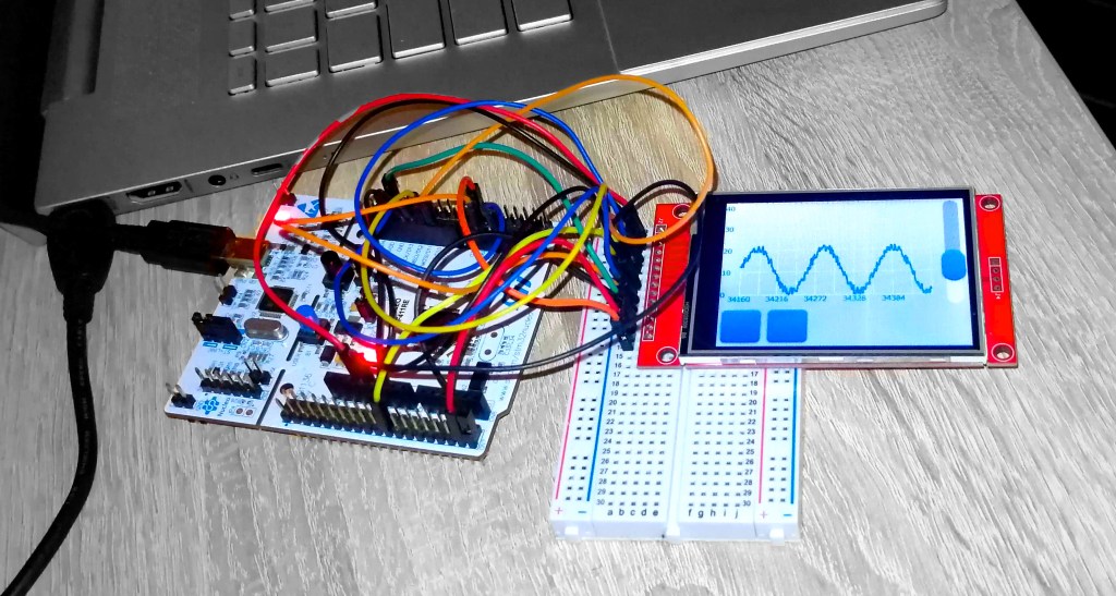
To make it happen, I used a DynamicGraph function in the TouchGFX Designer. I also added a slider in order to scale the y-axis, just in case the data value is too small/large to see. The data would be generated by the ADC configured in the DMA mode. Basically, I would set the ADC buffer to the size that matches the number of data points on the graph. When DMA requests an interrupt, the data buffer would be transferred to the TouchGFX AL for plotting. Here’s how I did that.
After selecting a proper size, color, etc. in the TouchGFX Designer, and generating the code I needed to adjust some the following code in the TouchGFX/gui/src/screen1_screen/Screen1View.cpp:
- Data transfer to the TouchGFX, at every second engine tick, using the addDataPoint() function. Unfortunately, this function requires point-by-point transfer, so I do it in a for-loop. Hopefully, they’ll implement passing by reference (address) in the future.
void Screen1View::handleTickEvent()
{
tickCounter++;
// Insert each second tick
if (tickCounter % 2 == 0)
{
  // Insert data point
  for (int i = 0; i < 280; i++)
        mojGraf.addDataPoint((float)adc_data[i]/4096.0f *100);
}
}- Setting the y-scale based on the slider value. This is basically an option to set the range and number of divisions of the y-axis only. Range is corresponding to the slider value, and the y-ticks come in interval of 10 for lower range and 20 for higher range.
void Screen1View::sliderValueChanged(int value)
{
// Adjust the Y-axis max value according to the slider value
mojGraf.setGraphRangeY(0, value);
mojGraf.invalidate();// Adjust the interval of the labels/grid lines on the Y-axis
// to match the new range.
if (value > 199)
{
    mojGrafMajorYAxisLabel.setInterval(50);
    mojGrafMajorYAxisGrid.setInterval(50);
}
else if (value > 100)
{
    mojGrafMajorYAxisLabel.setInterval(20);
    mojGrafMajorYAxisGrid.setInterval(20);
}
else
{
    mojGrafMajorYAxisLabel.setInterval(10);
    mojGrafMajorYAxisGrid.setInterval(10);
}

mojGrafMajorYAxisLabel.invalidate();
mojGrafMajorYAxisGrid.invalidate();
}
That was basically all. The global variable adc_data is the ADC buffer where DMA stores the data, using the call HAL_ADC_Start_DMA(hadc, adc_data, ADC_BUFFER_LENGTH). In the Callback function, the DMA transfer is simply re-set. The results are pretty good, I would say. The new data is displayed with the decent framerate, virtually matching that of the low-cost oscilloscope. There is a plenty of work to implement the properly functional oscilloscope using a TouchGFX, but that is far outside the scope of this post. I only intended to make partial framebuffer easy to grasp and implement on my board.

I accidentally found this blog, since Agilent 8753A is my favourite Instrument as well, but I didn’t expect this! Man, You’re a geek H/(P)ero! Great job!
Great Job….You are the Only in the world touching this topic, TouchGFX with SPI on simple Microcontroller(without LTDC).
I want to use ILI9488 , 320X480 without Touch display. I already Running it with a library by lcdwiki.com . Its working fine with STM32F303CB controller. I able to display the text and pics to the 3.5″ screen.
But that library has lack of Aesthetic look. I tried LVGL also, it says i have lack of RAM memory (No Luck).
Could you please help me, in the integration part of TouchGFX with SPI dataTransfer where it is actually to be written??
I dont need Touch, I just want to display the values from the variable running inside the functions with the screen of TouchGFX designed. Please help me in this regard, I spent so much time on this thing. You are the only Hop for me.
Thank you very much.
Fully agree, this is a very easy to understand introduction!
But just to correct your statement: STMicroelectronics does the same since mid of 2020 and provides a X-NUCLEO-GFX01M1 with ILI9341: https://www.st.com/en/evaluation-tools/x-nucleo-gfx01m1.html
It is supported by TouchGFX and there is also a software package called X-CUBE-DISPLAY available: https://www.st.com/en/embedded-software/x-cube-display.html
Great Job….You are the Only in the world touching this topic, TouchGFX with SPI on simple Microcontroller(without LTDC).
I want to use ILI9488 , 320X480 without Touch display. I already Running it with a library by lcdwiki.com . Its working fine with STM32F303CB controller. I able to display the text and pics to the 3.5″ screen.
But that library has lack of Aesthetic look. I tried LVGL also, it says i have lack of RAM memory (No Luck).
Could you please help me, in the integration part of TouchGFX with SPI dataTransfer where it is actually to be written??
I dont need Touch, I just want to display the values from the variable running inside the functions with the screen of TouchGFX designed. Please help me in this regard, I spent so much time on this thing. You are the only Hope for me.
Thank you very much.
Off All the ST engineers working in TouchGFX… , you did a very needed thing… Thank you very much.
Looks nice, please tell me how to implement a tsc2046 resistive touchscreen for an 800×480 display with TGFX. Thank you.
Hello
Could you explain why your block size is only 1920 bytes, while your framebuffer should have 150kB ?
Thanks
Amazing article, covering what the touchgfx documention lacked. Thank you so much!
I was wondering, since the sync serves to only unblock the engine to render the next frame when a transfer is done, why not use the DMA interrupt that tells us we are done transmitting by SPI?