Introduction
There are many, many, and many posts online about how to use Arduino board to program everyone’s favorite Atmel AVR family of the microcontrollers – Atmega. I haven’t made many microcontroller circuits from the scratch so I never had any real programmer, as for instance AVR ISP or USBtiny. But recently, I decided to make an Atmega168 based capacitance meter for my students and I was to lazy to purchase any of these programmers. Instead, I decided to use my Arduino Duemillanove board, and I had plenty of resources as those linked in 1st sentence. As always, things didn’t go smoothly and here I present my experiences and frustrations and the ways I solved them.
Capmeter + Arduino?
My students really love capacitors and what kind of lousy teacher would I be if I don’t make them one decent capacitance meter (capmeter, for short)? With that in mind, I roamed the Net in search for already made capmeters and stumbled upon this one. It’s a capmeter that measures time constant τ in charging cycle of the capacitor, has resolution of 1 picofarad and measurement span of 10 milifarads. But I won’t talk about it now, more details can be found on Mr. Pontoppidan’s site. I used the same schematics and C-code, only in my adaptation Atmega168 chip and FECC1602G LCD were used. His code was so extensive, complex and dannish-commented, I didn’t have the balls to change it.
According to the Arduino website, it should be a piece of cake to upload the code on the Atmega168’s Flash memory using Arduino board as a programmer. Four steps: first, upload “ArduinoAsISP” sample code onto your Arduino board. Second: wire the SPI ports according to the schematics here. Third: choose the board in Arduino IDE Tools that corresponds to your Atmega (in my case it was Arduino Duemillanove with Atmega168), and fourth: open the code in Arduino IDE, burn it, enjoy and tell you family how awesome engineer you are. In reality, get ready for 36 hours of headache.
Troubles and how to shoot them
- Code compiler. As you can see on Mr. Pontoppidan’s site, he uses good old C-code of a decent complexity and, oh gosh, some assembler parts as well. The source code was complex enough and I was lazy enough to turn down any idea of modifying it – so I just took it for granted, as many people successfully did, judging from the comments on the site. Declaratively, C-code should not be a problem for Arduino, after all, Arduino is written in C++, and the “language” we use when programming Arduino is “merely a set of C/C++ functions“. However, Arduino IDE didn’t want to compile Pontoppidan’s source code. I think it was because of library incompatibility of Arduino software and older code version Pontoppidan was using, or maybe something else. So I had to turn to some other compiler/developer environment and I chose WinAVR. It’s free software development tool for the Atmel AVR series of RISC microprocessors hosted on the Windows platform. It includes the GNU GCC compiler for C and C++. In the end, I still use Arduino board as a programmer, but WinAVR as a development tool.
- Compiler version. This was the last distress I had, when, ultimately. all of the following problems were solved. So, the latest version is 20100110 (from 2010) but is no good for Pontoppidan’s source code from 2006. It compiles the code, it creates all .hex and .elf files, it burns the code onto the AVR’s Flash, but the program doesn’t work. All I got was a nonsense displayed on LCD screen. So, my first guess was that compiler version is not suitable. I spent some times finding the right one – many of them do not support all Atmega chips. Finally, 20070525 worked fine for this.
- Multiple source files. I was trying to generate a .hex file of a project. I have used the MakeFile utility to create the makefile (the file that links the code I wrote with microcontroller I am using, all its registers and pins). Now, when I tried to run a make (using Programmers NotePad as well as from command Prompt) I got the following error message:
makefile:535: *** multiple target patterns. Stop.
My jaw fell down as I hopelessly watched the cruel white words on black Command Prompt background. I had no idea whatsoever where this could have come from. Fortunately, after some google searching, I understood what is it about. You see, Pontoppidan’s source code consists of two source files, main.c and lcd.c. If there was only one, main.c, in makefile would be written:
TARGET = main
SRC = $(TARGET).c
and everything is compiled without problems. But soon as you add additional source file, second line would look like:
SRC = $(TARGET).c D:\path\of\the\file\lcd.c
and apparently, it was source of error. To get rid of it, you should erase the path and leave only
SRC = $(TARGET).c lcd.c.
This tremendous help I have found on this forum, and I’m using the opportunity to thank DaddyTorque: who ever you are, may the God always compile your code error free.
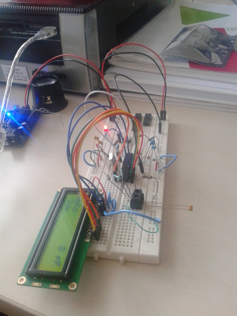
- Arduino autoreset. Once my code was successfully compiled and main.hex was created everything was ready for real chip programming. With the circuit assembled and wires connected like on the photo above, I opened Command Prompt, navigated to the folder where the source files were, and typed
avrdude -p m168 -c avrisp -P com3 -b 9600
which should open AVR’s programming hmm program avrdude, and make it connect with the Atmega168 microcontroller (-p m168a) via AVRISP programmer (-c avrisp) which is actually the Arduino board on USB port 3 (-P com3) at the rate of 9600 baud (-b 9600). We should get a nice message about how nicely we connected with the Atmega168. And of course, it didn’t work. Instead, I got error messages, such as
avrdude: stk500_getsync(): not in sync: resp=0x30
avrdude done. Thank you.
which you get when communication with the chip is not working. This usually indicates that you messed up wiring with Arduino or power supply or something, but in 1% cases, like this one, it is caused by the Arduino’s autoreset feature. Needless to say, I checked the wirings about 100 times and googled the problem for a long long time till I got the the page that talks about autoreset problems at Duemillanove board.
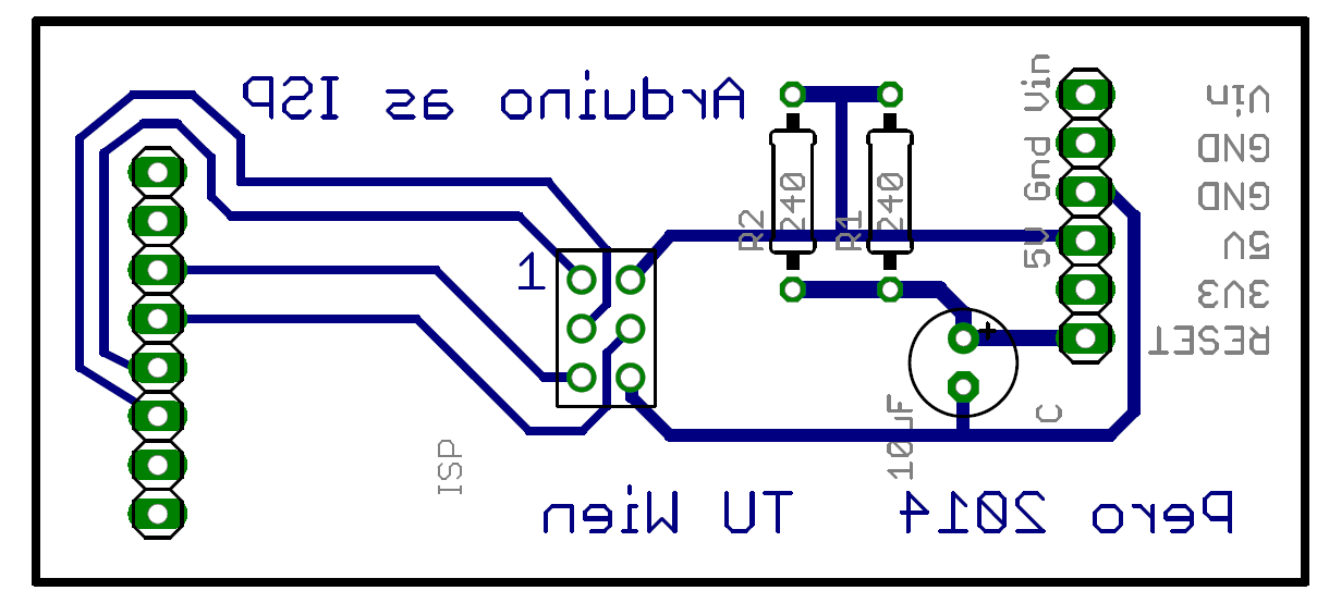
So, in principle Arduino resets when its RESET pin shortly pulses to ground. This happens when serial communication with the Arduino from PC is initiated, as when a program (avrdude) connects to a serial port. Avrdude wants to connect to the Arduino before it has booted. During this time, RESET pin is pulled to ground and you want to keep it on 5V for the time of burning the flash. To solve this, stick 120 Ω resistor between 5V and RESET pin on Arduino board. Try to be as close as possible to this value – too big resistance will work as a pull-up and reset can be caused internally, too small resistance will make big current flow to the ground as RESET pin is being pulled on ground. I used two 240 Ω resistors in parallel. For additional stabilization it is good to put 10 µF capacitor between Arduino’s RESET pin and ground. More info is here.
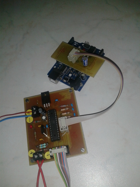
Finally, I made a small PCB which can be used for programming AVR’s from Arduino in general. Every project I make from now on with AVR chips, I only need to add 6-pin flat cable connector and use the board+Arduino as AVR in-system-programmer.

One thought on “Programming Atmega μC with Arduino – Troubleshooting”