Introduction
The coolest sounding theory in modern science is definitely the Chaos theory. No one is quite sure what it stands for, but we like to use the phrase to say that something is messy and there is no convenient way to describe it. And butterfly, there is always that butterfly whose wings can cause a hurricane on the other side of the globe. However, the thing with the chaos is that it is very describable, and up to some very high point predictable, and there is no easier way to experience it from the first hand than by constructing Chua’s circuit. The very simple circuit that enables you to observe patterns of chaos from the first row on your oscilloscope.
Chaos… is not so chaotic after all
We use the word “chaos” when something is apparently in the state of disorder, lacking any common sense or common logic. Examples of what we could call a chaos are weather, stock market, our work desk, our closet and our girlfriend’s emotions. This may be a kind of poetic view on “chaos”. Mathematical view on chaos is, however, more precise: chaos is a system extremely sensitive to the small changes. Slight turbulence somewhere (butterfly wings) may cause incredibly large outcomes (hurricane) if the turbulence was not present.
Ok, maybe the butterfly and the hurricane are not that easy to illustrate; try with the double pendulum. One pendulum hangs on the other, like on the gif. As they swing they trajectory makes these cool looking curves – something you may want to consider for yor next tattoo. Now change the initial conditions just a little bit. The trajectory now looks completely different. Still like on drugs, but much different than it used to be. Now you see what the chaos theory is all about – modeling systems where teeny tiny woopsie doopsie change leads to the enormous variations in final result. I hope you can imagine now why systems as a macroeconomy, weather forecast, many-bodies problems in physics are considered chaotic systems. Even though we have math and we have the formulae, we still can not go that deep to calculate the final result. And not only us, our best computers can not do that. The best we can achieve, to keep on observing and use our very natural human talent: pattern recognition. In every chaotic system, no matter how complex it can be, patterns emerge and we can have some insight on what could be happening in a while.
Build your own chaos – Chua’s circuit
To quote wikipedia, Chua’s circuit “is a simple electronic circuit that exhibits classic chaos theory behavior. This means roughly that it is a nonperiodic oscillator; it produces an oscillating waveform that, unlike an ordinary electronic oscillator, never repeats”. Very insightful design guide is given on its “official” website. Basic circuit looks somewhat like this:
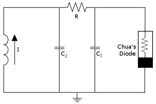
As you see, it has one inductor, some capacitors, so it must be some kind of a resonator. The crucial part is the component called Chua’s diode (even though it has nothing in resemblance with the common diodes) which has a non-linear voltage-current characteristic. This non-linearity is what makes the oscillator “unrepeteable”. Let’s put current of Chua’s diode to be some non-linear function f(V) of voltage on its ends. If we designate voltages across 


What do we see from these equations? We see that if we time-derive first one, and plug in the second one we’ll have something in a form 


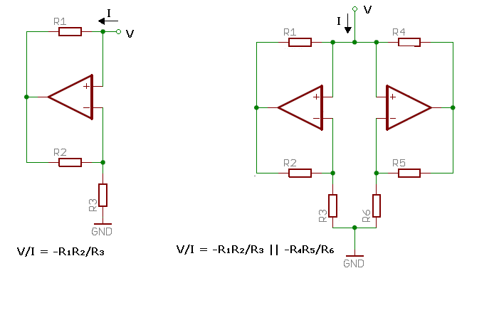
Did you notice how the current is negative when the voltage is positive on Chua’s diode? And vice versa? It doesn’t seem as usual. And it’s not. This is the reason why the component is said to have a negative resistance. I’ll let you philosophize on what it means. Just imagine, you are pushing current in one direction, but it comes way back to you. The engineers have come up with the circuit that models negative resistor using operational amplifiers, and on the image below is how it looks like. However, one negative resistor gives us one slope of Chua’s diode function, and we need two. What do we do now? We push the amplifier in the saturation. We put the gain so high that for the voltages above E and lower that -E output is alway +Vs or -Vs (power supply voltages). Then, at the same time, we add another negative resistor in parallel so that it defines the slope in the regions where the first one is saturated. By trimming the component values, we get the desired transfer function of Chua’s diode.
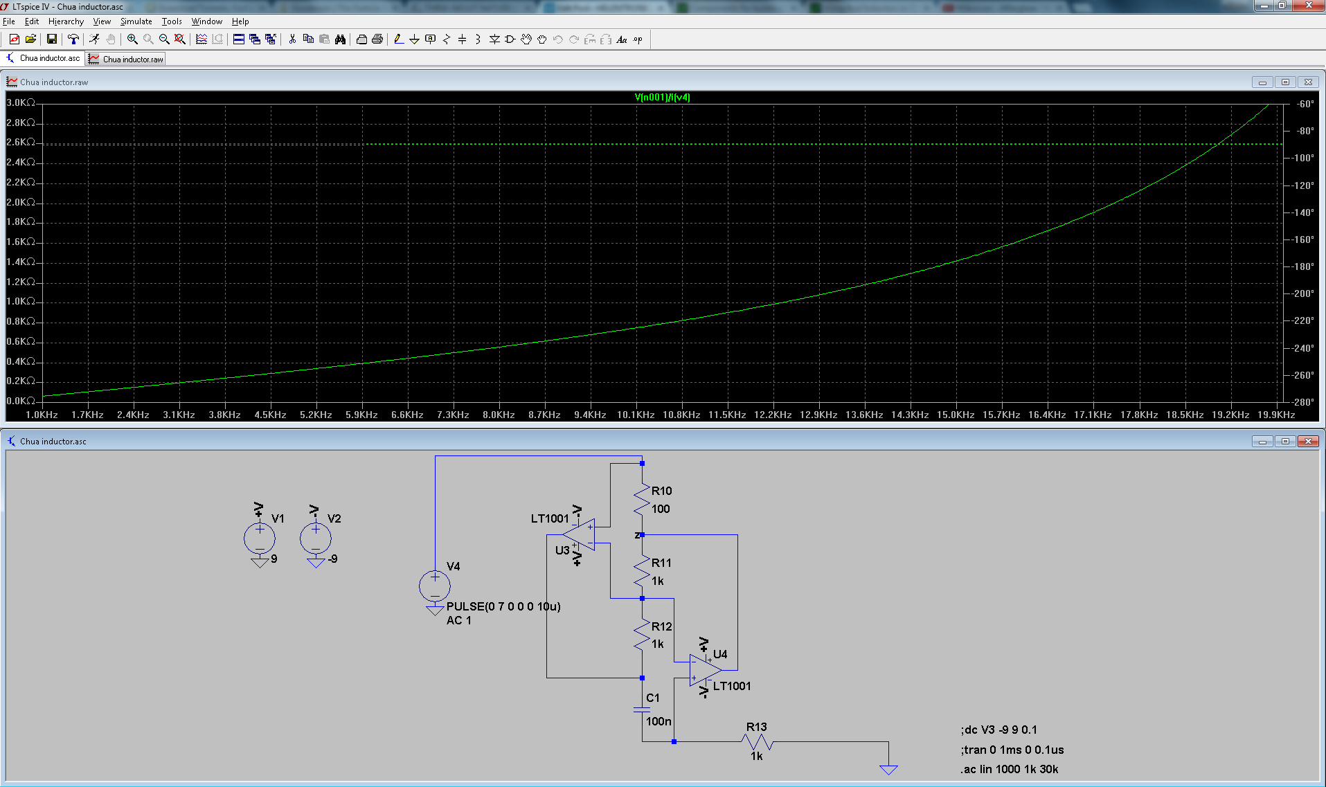
Much more complicated issue is the inductor on the schematics. Yes, the stupid small inductor. In order to make the resonator work we must be very picky with the component values, and the inductor is the most sensitive one. In e. it should have an inductance of 

Enter gyrator
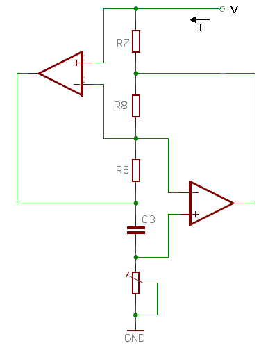
Gyrator, or the “fifth linear element”, is a very handy circuit that enables us to build idealized versions of components such as inductors, transformers or capacitors. Yes, you read it well – we’ll use a bunch of op amps, resistors and capacitors to build a simple coil inductor. Basic inductance-simulating gyrator circuit is here, while more advanced one, the one we’ll use in this project is in the image on the right. I tried to do the math for the impedance expression, but very soon I got really messy and decided to rather make a simulation in LTspice. Results can be seen below.
Putting it all together
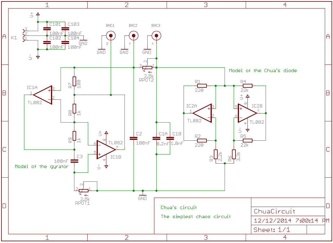
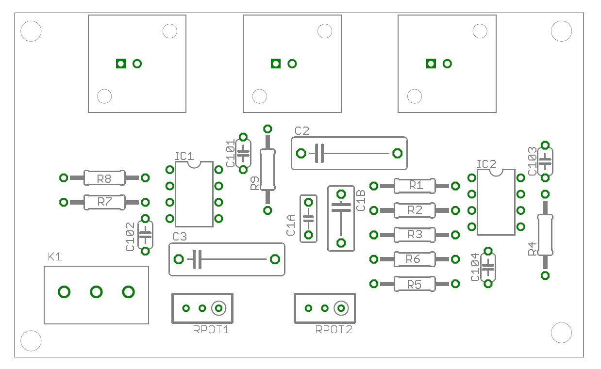
Okay, now would be time to assemble everything together. Inductor we have, Chua’s diode also. Operational amplifiers I used are quite generic TL082. In the end, the source recommends usage of the foil capacitors over the ceramic ones. Final schematics and component layout is here:
How it looks like after the board development and soldering:
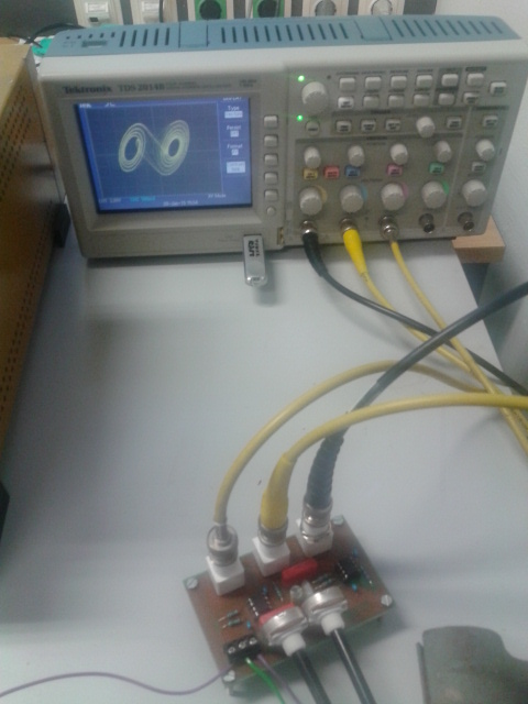
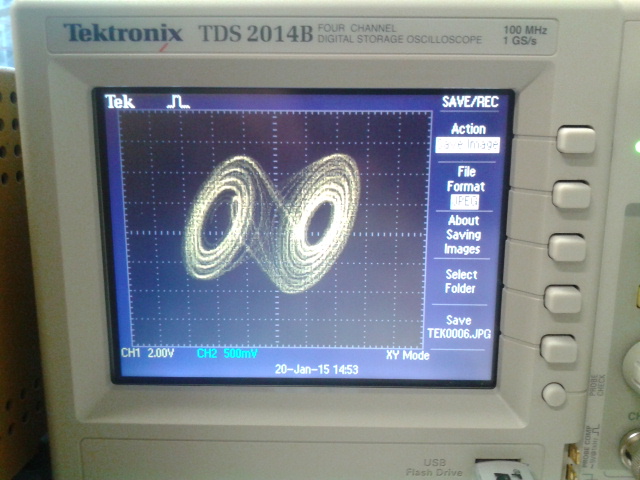
This photo, I believe, tells you everything. I used +/- 9V from the lab power supply. To get the image like one on the photo, you would need to carefully adjust potentiometers. Keep in mind that Chua’s circuit does not always oscillate – only when your potentiometer adjustment is so good that it satisfies oscillation condition. We have 3 outputs, x,y and z from the schematics at the BNC ports. In ideal case they look somewhat like this:
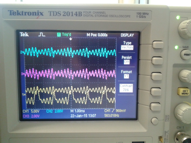
Once you got the image like the one on the photo, turn your oscilloscope into the x-y mode of x and y channel, and observe how the double scroll pattern revels in front of your eyes!

Why not implement the whole thing in software? Your scope shows the waveforms cycle at about 3 periods per millisecond, that’s 3 kilohertz. If you wrote software to continuously integrate the differential equations at 15 microsecond intervals, that’d give you 22 points per cycle. Plenty enough to reconstruct the fundamental and the first 10 harmonics.
Run it on a Raspberry PI which achieves 40 megaflops, done. You get 2667 floating point operations per timepoint, way WAY more than enough to integrate the diff eqs.
I’d agree with you, it should be feasible to run it on RasPi. However, I am not sure how well can you “tune” the coefficients. The expensive potentiometers I’ve bought for this project enable me very fine tuning and reaching oscillation. If you manage to do something like that, please, keep me noted.
I did find a coil that’s 18mH and lower then 25 ohms
http://uk.farnell.com/coilcraft/rfc1010b-186ke/inductor-power-18mh-0-21a-10/dp/2457933
For 50 cents it’s not that expensive either, does the schematic work without change if I replace the gyrator with the coil or do you think something else has to be changed?
Well, the guys on chuacircuit.com do say that you can use some very special coils which can be purchased more easily than they were 30y ago when the circuit was designed. It could work, so I encourage you to give it a try. What I find unsatisfying is that you can not tune it as with gyrator, and this circuit is very sensitive on such adjustments.
chuacircuit.com is suspended. where else might i find these guys?
http://www.chuacircuits.com/inductors.php