Introduction
There are many hobbyists out there who made their own reflow soldering machine, like this guy, or that guy, or this dude, that pal etc. It made me realize that if you want to be somebody in electronics you should have your own DIY reflow machine. It’s also a good opportunity to clean some rust from your knowledge about automatics, control theory and cooking. The standard flowchart in making one reflow machine starts with purchasing some really cheap, old toaster oven for 10 bucks, building some microcontroller circuit and programming it to work as the PID regulator. Of course, if you know, a priori, what do you want to solder and how the temperature profile should look like. So, in the next few posts I’ll try to lay down my approach in designing one reflow oven, starting today with the cheap toaster oven analysis.
Dirty little oven
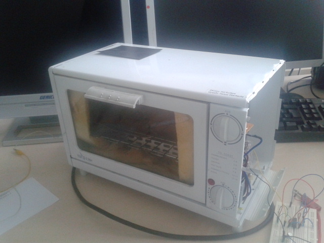
As usual, it begins with finding some cheap toaster oven. These things you can find in almost any online advertiser, 2nd hand shop or similar. These things usually come in size of 0.5m x 0.2m x 0.3m, are full of food stains and crumbs from an untidy previous owner, and are generally used for fast food heating. Perfect thing for soldering!
I found mine on some local advertisement, it costed me 10€ and, as expected, the owner didn’t have any documentation nor knew anything about it. So I picked it up and brought to my lab for the further analysis.
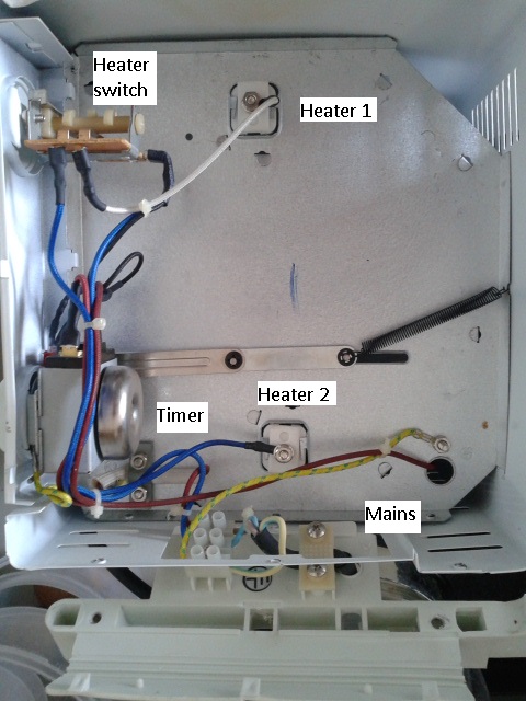
First thing, of course, is to disassemble it and see what it has inside. Apart from the food crumbs there are two heaters, timer relay and an indicator bulb. The idea was obviously to control heat strength by turning one, both or none heaters with the top knob directly from the mains power socket. In the series with the heater comes the timer relay that is shorted only when it tick-tocks for the time we can choose, and the bulb that shines only when the toaster is on. Quite simple, right? Here is a simplified schematics of that. I immediately decided I don’t need the timer relay or oven test, so I plugged the wires out of it and shorted. Now the electrical current will go directly to the heater.

Big question is: what is the heating power of the oven? We can safely assume that all of the electrical power delivered to heaters will be dissipated into the heat. Here in Europe, power grid is on 230V RMS. Measured resistance seen from the power chords is 80 Ω what makes total power of 230^2/80 = 660W, a reasonable value for a toaster oven.
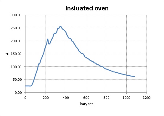
Now I needed to thermally characterize the oven. What’s the maximum temperature that can be reached inside? At which rate does the temperature rise? Are there any insulation leaks? Convection? The easiest way is to plug the oven in the wall and wait. But before that, let’s put in a digital thermometer to get the data at every point in time. What I got is plotted here:

And there we see a nice exponential growth to 250°C. Why is it exponential, you may ask. Well simply, because the air inside and everything else inside has a non-zero heat capacitance. It takes some time till the heat fills up all air and its temperature reaches its peak value. You can even simply model this analogously to the electrical RC circuit. The temperature in the middle is “voltage” on the capacitor, and power (600W) is a “source current”. In steady state, so when the temperature is non-changing, we can define so-called thermal resistance which is calculated as Temperature change/Power and here it equals 0.375 K/W. Not very bad. What is more problematic is the heating rate. If we interpolate the measured curve with something like 


Warm me up!

The most reasonable thing to do is to improve the oven’s insulation. Luckily, around my lab guys are repairing the building windows and there is a lot of popular isolation material lying everywhere – the glass wool. I picked up few pieces and placed them in the oven, just between the heaters and the chassis. What will the glass wool do? It will prevent the air convection – one of the biggest heat leaks in the oven. Just because of the wool, the air can not circulate as easily as before so it will mostly stay in one place and absorb the heat. This should drastically increase temperature rise.
One really important thing now. As the glass wool is in direct contact with the heaters, it will obviously melt at the point of contact. Once cooled it will stick to the ceramic coating of the heater and increase its own thermal resistance. That can lead to the heater’s overheating and finally its destruction (in terms of melting down, or simply breaking). So I put a piece of aluminum foil along the surface of contact, as you can see on the right photo. Now it should all be nice and cozy in there.
Soon after turning the oven on, you could smell something really ugly and toxic burning. It was of course the glass wool melting and, hopefully, it was harmless. Intensive red light indicated that it must be hell inside, and the thermometer showed a rapid increase in temperature.
As you can see on the graph, the oven reached the 250°C in less than 5 minutes. Remember that without the glass wool it took more than a half of hour. And to make things even crazier, this isn’t even its final temperaure – I turned the oven off when it reached 250°C to prevent any further damage. Anyway, the maximum temperature rise is about 70°C/min with the cooling time constant of 500 seconds. Now, this is something easier to control with the future PID regulator.

One thought on “Analyzing cheap oven for the DIY reflow soldering oven”