Introduction
In my previous post here, I analyzed cheaply purchased toaster oven that will be used as a reflow soldering oven. In order to make a good reflow oven, with a good PID regulation, we need to know it’s dynamical properties. While in the last post I played with, let call them, static characteristics, the dynamical properties will be analyzed in this post.
How to control the oven?
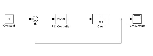
So, the deal with the control is to bring the temperature at the desired value as soon as possible. Or, better said, as soon as desired. Left is the most typical control system, the one you’ve probably studied, like I did, in the early years at the University. The oven is represented as a dynamical system with a certain transfer function (the thing with lots of ‘s’). Controller’s role is to set up the input of the oven so that the temperature gets to the desired value. To do that, some kind of a feedback is necessary, some sort of temperature sensor, and in this case it will be a K-type thermocouple. More info on control loop theory is in this brilliant web-book.
The most popular type of the controller is so called PID controller and in the next post I’ll describe my attempts to design one. For now, it’s enough to know that it will run on Atmega microcontroller and it will work with PWM signals. What?
PWM control
Earlier I mentioned that the oven is powered by the mains electricity, which is in Europe 230V RMS, at 50 Hz. RMS, or root-mean-square, means that actual voltage is ugly sinewave with 230 
When we plug the oven to the mains, the temperature rapidly rises to above 300°C, as seen earlier. This is not very useful. For french fries maybe, but definitely not for soldering. So we need to reduce the input voltage to achieve smaller temperature. How to do it? I can not reduce the voltage from the mains socket, which is set by the power transmission system. Or can I?
What will happen if I periodically turn the oven on and off? The effective voltage will reduce. Instead of 230V it will become 230V 


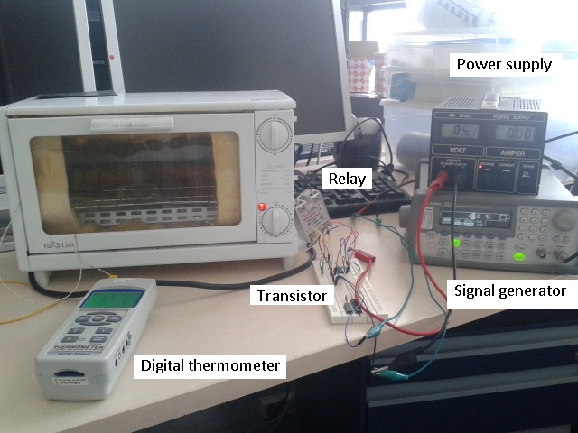
So, I replaced original timer relay and put my new solid-state one, found some laboratory signal generator and was ready to test. Just a second! To drive a relay we need some 10 milliamps of current, and that is much more than simple signal generator can give. That’s why I needed to put in some transistor switch in between, like in the schematics on the right. Finally, everything was set and ready to roll.
If you’re considering doing something similar, be very cautious in relay plugging. In my oven it was enough to connect it to the ports of previous timer relay. Sometimes it may be necessary to cut the power cable. In that case, only one wire should be cut (preferably the brown one) and its ends connected to the relay ports.
Measurement time
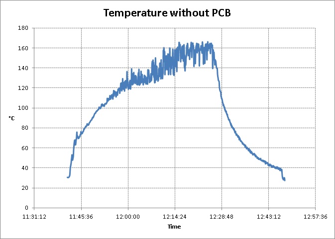
On the signal generator I set square-wave signal, period 250 ms, duty cycle 30%, amplitude 2V (that should be enough to drive the transistor). The first measurement was, unexpectedly, terrible. The temperature in the oven went crazy, somehow oscillating as it reached its peak value (picture).
Why was that so? I didn’t know at that time, but it was because of small “thermal mass”. What? Imagine simple mechanical spring. If you shake it, it will bounce like crazy. But if you put some heavy load on it, it will be much more stable. The similar works here – I am transferring heat through the air, and you can imagine it is very low thermal load. And since we are using PWM control, we have some dynamic response. Just like the spring with no mass on it, so is the temperature in the oven unstable. The solution? Put some mass inside. Some small mass, in e. the spare PCB, just like the one I intend to solder later. Here are the new results, with duty cycles of 20, 30 and 40 % ( I was afraid to use more, since it could be dangerous for the heaters).


Here you can see some nice responses. After interpolation (simple in MS Excel), I found out that they all correspond to the PT1 system whose time constant is 300s and gain 0.9 K/W. Remember, PT1 system is such system whose step-response looks like
![y(t) = Y_0\left[1-exp(-t/\tau)\right]](https://s0.wp.com/latex.php?latex=y%28t%29+%3D+Y_0%5Cleft%5B1-exp%28-t%2F%5Ctau%29%5Cright%5D&bg=ffffff&fg=232323&s=0&c=20201002)
where 


Very nice, isn’t it? One of the rare situations when things in the lab work in accordance with some basic level theory.

One thought on “Analyzing cheap oven for the DIY reflow soldering oven – part II”