Introduction
There is this USB specialized family or group of everyone’s favorite AVR microcontrollers. Apparently, you can use them as USB devices or hosts without any external components. Hell, you can even program them via USB port. All of that without any external component. One of those little guys I wanted to use for my last project (reflow oven) and I decided to try the cheapest one, ATmega8u2 as a controller. I ordered some pcbs, some components, soldered everything together and started programming. But the tiny little ATmega8u2 didn’t like the idea…
AVR USB microcontrollers
Few years ago, beloved family of Atmel’s AVR microcontrollers got a new branch in its family tree, the USB mega. Some of the most popular were AT90usb82, ATmega32u2 or ATmega32u4, differentiating by size of Flash memory or number of peripherals. They would have fully embedded USB capability allowing them variety of beautiful possibilities – they could act as the USB devices at your PC, they could be USB controllers for many peripheral devices in e. keyboards and mice, printers etc. You’d just need to solder the standard USB connector next to them, put two lines, and magnificent world of USB would be opened for you. Best of all you could program them directly from your PC, over the USB cable. That’s right. No programmer in between or any other piece of hardware (looking at you, FT232). That was the magic of embedded USB that not many could master.
Getting clear with the names
So, when they came out, not many people could work with them. USB protocol is hard to understand and even harder to implement. I’m not sure if Atmel published any getting-started documentation or anything useful but it was as good as nothing. I found myself in the same desperate position few days ago when I wanted to make fully USB operable circuit with ATmega8u2. I searched up and down for any help, how to make the damn USB work, I read every post on AVR Freaks forum. I got totally confused with all the things mentioned apparently without order, DFU, CDC, probably 3-5 definitions of firmware and boot loader, Flip…
So, to make things very short, every microcontroller on this world may be programmed to the the stuff we want. The software that sits in the μC’s Flash memory is called firmware and we put it there via small device called programmer. The programmer uses either ISP (in-system-programming) port or JTAG port to “put the code” in flash memory. “Putting the code” in the flash memory of the microcontroller is often referred to as burning the flash, flashing or simply, programming.
Atmel’s USB microcontrollers brought a novelty here – they made it possible to burn the flash without programmer, simply by connecting USB cable from PC to μC. To do that we need something called a boot loader. The boot loader is a piece of firmware that already sits in the μC’s memory and is able to talk to your PC when you plug in the USB cable (or any programmer). They have disadvantages however; they cannot change the fuse bits of the AVR (special configuration settings that control the operation of the chip itself) and a small portion of the AVR’s FLASH program memory must be reserved to contain the boot loader firmware, and thus cannot be used by the loaded application. All of the USB AVRs like ATmega32u2 or AT90usb162 come with the USB compatible boot loader already burned on them when you buy them so you don’t need to think about it. Just write your code and program the Flash. All of them except one, and of course Mr. Murphy, that’s the one I was using, ATmega8u2.
ATmega8u2 comes empty, naked, virgin, with nothing on it. On a hard way I learned the tricky part where you need to burn the bootloader in the flash before you can do anything meaningful with it, and this you do with conventional ISP or JTAG programmer. Though sometimes the chips can be bought with the bootloader already in the memory, a lot of times you have to do it your self.
USB Boot loaders for AVRs
I hope you are clear by now that if you want to have a USB programmable microcontroller without additional components, you need to burn some sort of boot loader on it via ISP or JTAG first. For USB based AVRs there are few boot loader options and excellent overview of them is given by Lincomatic.
- DFU – USB Device Firmware Upgrade Class
Once you burn it, the Windows will recognize it as a “Atmel Device” on your PC. Then can use Atmel FLIP tool to burn .hex files on it. You have probably encountered this if you have ever tried to update boot loader on Arduino UNO. Downside is that no command line tool is available for Windows. For Linux, an open source host loader app is available. And you can’t integrate it into Arduino IDE. DFU boot loader comes in almost all off the shelf USB AVRs.
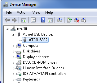
Once you burn the DFU bootloader on your AVR chip, the PC will recognize it as a Atmel USB device… 
..which you can program via Atmel’s official tool called FLIP.

- CDC – USB Communication Device Class
Once you burn it, the Windows will recognize it as a serial port (so called virtual port) on your PC (LUFA CDC Class Boot loader). Then you can burn .hex files of your program on it with with avrude via avr109 protocol, which also means that you can integrate into Arduino IDE. The command I used for programming was the following one:avrdude -p usb82 -c avr109 -P COM7 -b 19200 -U flash:w:MyHexFile.hex -F
avrdude doesn’t have ATmega8u2 on its list so I use AT90usb82 to fool it. The -F at the end prevents signature check so that avrdude doesn’t make troubles out of this incompatibility.

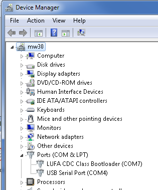
Window beautifully recognizing CDC bootloader AVR as a COM port… 
…that you can easily program with standard tools like avrdude

- HID – USB Human Interface Device Class
This one I haven’t tried because I couldn’t have it burned – .hex file was larger than the Flash of ATmega8u2. Here’s what people say about it: PRO – Trouble free – doesn’t require any device drivers – just plug and play, CON- doesn’t integrate into Arduino IDE
DFU and CDC require special drivers to be recognizable by the Windows, while HID, apparently works like a charm. To find those drivers on your own can be a pain in the ass but usually they are packed in Boot loader edition folder.
To sum this part up – to work with your USB AVR you need to have a boot loader on it. The boot loader either comes on it when you buy the chip, or you burn it yourself with ISP. You can choose between three USB compatible boot loaders: DFU, CDC and HID. For the first two you need a driver to make it recognizable on your PC. Then you make your program in regular way (with Atmel Studio, WinAVR, or smtg else) and generate the .hex file. Using simple USB connection, you can burn your program onto the AVR’s Flash either by FLIP or avrdude, depending on the boot loader type (HID I haven’t tried yet).
Once you have your program burned on the chip’s memory, it will execute every time you power your circuit. The boot loader will not execute anymore and your circuit won’t be visible on your PC. If you’re unhappy with your program and want to re-program your chip, you need to get back to the boot loader – make it visible on PC once again. This you do simply by reseting the chip – ground the RST pin for a few seconds and the chip will get back to its boo tloader. It’s almost the same as when you open the BIOS system on your Windows PC.
Fuses, fuses they give me bruises
I bet you ran to your work desk immediately to start programming, aren’t you? Well, not so fast! This is what I did and failed. I burned the CDC boot loader, compiled my application and tried the upload it..and everything crashed. So, I had to get back to studying somethin more about AVRs.
There is one more thing you need to be careful about, so called fuse bits. Fuse bits are parts of permanent system registers that describe how will the μC interact with its surroundings. What do you need to know is the hexadecimal value that gets to be written in those registers. Luckily, there is a very neat calculator of fuse values for almost all AVR chips. There are three kinds of fuses: low fuses that determine the clock type of the system; high fuses determine the memory distribution (very important when working with the boot loaders) and extended fuses that determine the brown-out detection (what’s the supply voltage drop that causes internal shut down). In example, when I am using ATmega8u2 and I want to have an external 8 MHZ oscillator, undivided (low fuse value is 0xFF), boot loader section in Flash memory size of 2048 words (high fuse value 0xD9) and brown-out detection at 2.7V (extended fuse value 0xF6), I’ll have to write in my avrdude interface:
avrdude -p usb82 -c avr109 -P com7 -b 19200 -u -U lfuse:w:0xff:m -U hfuse:w:0xd9:m -U efuse:w:0xf6:m -F
If I want to check the value of my fuse bits, I simply go to avrdude terminal mode (avrdude -p usb82 -c avr109 -P com7 -b 19200 -F -t) and type “dump lfuse” etc.
Now that we’re speaking of fuse bits there is another important permanent register we need to take care of when working with the boot loaders. What I learned on the hard way is that sometimes, during the programming, the boot loader can store the application code over itself! I.e. it will write the application code over the boot loader section of the Flash memory. This is really bad, because next time you reset your chip, you won’t see your boot loader. It’ll be gone, for ever. To prevent this mishap, there is another set of bits called lock bits. They make sure that no application code gets stored into the BLS section or vice versa. They can even block the programming of the entire application code. The details about their value are in the μC datasheet, but generally, if I want to prevent BLS from self-programming, I need to write 0xEF in the lock register:
avrdude -p usb82 -c avr109 -P com7 -b 19200 -u -U lock:w:0xef:m -F
Now that you have studied the data sheet, calculated fuse values, new problems start. When you write down the command from above, some verification error arises, something like:
avrdude: verifying ...
avrdude: verification error, first mismatch at byte 0x1000
         0xef != 0x3f
avrdude: verification error; content mismatch
This one gave me a lots of headache. What does it even mean? Anyway, after browsing AVRfreaks forum, I learned that this is perfectly normal and I need to inhale deep and calm down. The thing is that 0xEF in binary looks like 1110 1111, where only middle four bits are programmable. It means, that 11xx xx11 are fixed in the chips memory. But problem is when some chips instead of ones have zeros, so this register looks like 00xx xx11. I don’t know why or which rule does this appear but it appeared to me. So, instead of writing 0xEF (1110 1111) I needed 0x2F (0010 1111). After that everything worked like the charm and I get to upload my application with no further problems.

hi,
Thanks, for the giving a valuable information on ATMEL USB micro controllers
i am an engineering student and electronic hobbiest, new to this type of micro controller. I am doing a project which contains AT90USB1286 microcontroller, ADS7825(ADC 16-Bit, 4 CHANNEL), strain gage and with analog signal conditioning circuit. Hence, it is nothing but a data acquisition system
i need to transfer the data(processed strain gage data) from Micro controller to PC Via both UART and USB Modes. I wrote all the program and compiled successfully, i am able to transfer the data from AT90USB1286 microcontroller to PC(on Hyper terminal) through UART(RS-232) protocol.
i was using ISP protocol, kanda isp(driver software), stk200 dongle(which was made by my self).
i made my total hardware circuit on general purpose board and its working functionality is quite good.
i am able to program the AT90USB1286 micro controller. I was not using any DFU boot loaders/ FLIP etc.
i want to transfer the data(i.e processed strain data) from Micro controller’s inbuilt USB to PC via USB, I read through multiple documents including AT90USB1286 datasheet but i don’t understand them, maybe because i am a student and newbie to this type of micro-controller and no software background(except ‘ C ‘), What i would like to know is how to use the USB hardware build in AT90USB1286(to communicate with PC). and also is there any simple stand alone software, that i can use, write and send the data from AT90USB1286 to PC?.
i read LUFA-151115. Because of my poor knowledge, i am getting confuse that which one is suited to me among all examples which they provided and i don’t know how to use that library.
it is my kindly request you that please help me what i have to do to get transferring the data from AT90USB1286 to PC via USB.
if possible, please tell me the step wise procedure to get the data transfer from AT90USB1286 to PC via USB.
thank you in advance,
excuse me for bad english,
regards,
vasu
Hello Vasu,
sorry for the late response, I was on my honeymoon in South America and didn’t have a proper access to my site host. Now, if I understood correctly, you would like to use USB as a communication protocol between your AVR and a PC, right? If yes, good, that I can answer, because I’ve also struggled with it myself some time ago.
A good way to start it is to look up a Virtual Serial example in LUFA. In there you establish a USB protocol by initializing a Communications Device Class (CDC) and you can transfer text data using the standard functions fprintf and fscanf.